

Cyclone Exhaust Heads • Exhaust Silencers • Flash Economizer • Flash Separators
|
|||
For Horizontal Piping... HORIZONTAL T SEPARATOR Tangential Inlet - angled down to improve separator
efficiency. Stainless steel striking plate at inlet impingement significantly reduces sidewall erosion.
|
|
||
Satisfied Customers Prove Penn's Outstanding Performance
| Airco Products Argo Compression Service Corp. The Bouligny Company Browns Williamson Tobacco Co. California Peanut Co. Celotex Corp. C & H Sugar Cinti. Gas & Electric Co. Combustion Engineering, Inc. Curtis-Wright Corp. Dow Chemical Co. Frito Lay |
Frolic Footwear Company Gimbels Gulf States Utilities Holly Farms Martin Mechanical Corp. Midland Glass Company 3M Company Olin Corporation Paramont Foods Pawling Rubber Corp. Pennzoil P. Lorillard Company |
Research Conrell, Inc. Schering Corporation Shambaugh & Sons, Inc. Stanford University Steam Plant Stauffer Chemical Stone & Webster Engineering Corp. Suny at Stoney Brook Utility Block Co. West Feed Mill Wisconsin Power & Light Worthington Corp. |
Horizontal Inline
Gases and entrainment enter the separator and are quietly directed into a circular path by Penn's Helical Baffle, PHB™. "Quiet" is an important word because medium velocity gases flowing through vanes or slots can produce noise. Efficiency is also important. PHB™ develops maximum centrifugal force with minimum pressure drop, insuring good, strong, cyclonic spinning the entire length of the separator. Entrainment flows to the drain and flowing steam or gases escape clean, dry and free of entrainment through the central vortex outlet back into the flow line. Re-entrainment is restricted because the drain baffle develops a boundary layer which separates flow area from entrainment area. Dimensions are available on Spec. Sheet IH418 - R4
Some Particular Problems Penn Has Solved
| Penn Takes The Lumps Out Of Sugar The candy orange slice, coated with sugar crystals, has long been an American favorite. The California concern which coats these candies with sugar uses steam in part of the process. The steam often caused the sugar to lump until Penn inline separators solved the "lump" problem by removing the excess moisture. Penn got things going "smooth" again! |
Penn Protects Stainless Steel Kettles A leading manufacturer of canned fruits and vegetables in Kentucky had a problem with its stainless steel cooking kettles. The steam supply to the kettles contained too much moisture. This excess moisture combined with the pressure, was responsible for pitting the steel in the kettles. The company purchased a Penn Separator, which solved the problem. Since them, the company has purchased several more, knowing the separators will more than pay for themselves by extending the life of the stainless steel kettles. |
|
You'll find our factory trained representatives most helpful in helping you solve your particular problems. Don't hesitate to call upon their experience. |
||
 |
FOR VERTICAL PIPING DOWNFLOW Entrainment separation is easily accomplished in "down-comers" with the Penn Downflow Separator. Penn's Helical Baffle, PHB™ quietly develops clean, cyclonic spinning permitting reversal of flow to center vortex finder without picking up separated entrainment. Penn's Downflow Separator fits directly into the flow line and requires a minimum of space. Dimensions are available in Spec. sheet No. ID 418- R4 UPFLOW Penn's Upflow Separator is specifically designed for "pipe-risers". Note that special
treatment is given to the insertion of Penn's Helical Baffle, PHB™ so that an area exists
outside the main flow area where entrainment can flow to the drain area without being picked up by the main flow steam. The outer wall of the separator forms a boundary on which entrainment droplets continually collect and slip down into the low flow area and from there to the drain. |
 |
INSTALLATION AND PIPING IS MADE EASY WITH PENN SEPARATORS
| Installation and piping are simplified by Penn Separators because all separators are inline type. It is only necessary to allow for the inlet to outlet distance given for the specific type separator chosen. It is recommended that inlet and outlet supports be used on smaller units, and that on larger units (6" and above) the inlet and outlet supports be used in addition to a central pipe hanger support. |
Proper trapping in separators is most important so that separated entrainment can be readily drained from steam, air and other gases. The Penn installation sheet (INST-492) discusses this in greater detail. The trap selection charge (108A94, pC7- D7) simplifies selection for specific flow and other conditions. Penn's sales people are always pleased to assist you. Don't hesitate to give them a call. |
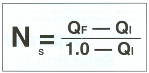
Separator Efficiency
|
|
|
Separator Pressure Drop The right side of Chart S gives maximum pressure drop. Simply read horizontally from separator size (at correct PSIA) and read pressure drop on right axis. |
||
Separator Selection For Compressed Air And Other Gases
As in the case of steam, in order to insure less than one-half percent entrainment at the exit of the separator, for particles 10 microns and larger, Chart A for air flow will yield the proper separator selection. Separator size is given for various operating pressure ranges for each flow rate specified in standard cubic feet of air per minute (SCFM). If the compressor capacity is expressed in actual cubic feet of air per minute (ACFM), a simple conversation to SCFM can be made using the following equation:
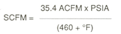
using the operating pressure and temperature.
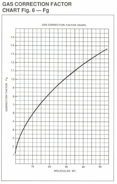
Corrections must be made for other gases (Fig. 6 page 8) before using Chart A (see page 8).
Separator Pressure Drop
To find the maximum pressure drop, simply read across from separator size to pressure drop on right axis of Chart A. If a lower pressure drop is required, ask our sales people for Inline Separator Sizing Sheet and for their recommendations.

| Optimization of Separator Size Through much research and development, Penn's engineers have optimized the design of the perforated cone component of the inline separator, resulting in increased efficiency over a tested range. As shown in the above graph, the actual experimental data shows that use of a Penn Cone halves the margin between the maximum, theoretical, cyclone separator efficiency and the efficiency occurring when no cone is used. This shows the advantage of "Penn's Unique Cone." Because of greater turbulence created at higher velocities, separation efficiency for all cyclone-type separators diverges from the theoretical (curve 1). Therefore, sizing charts should be developed by designing for the inlet velocity, which corresponds to optimum efficiencies. (See shaded area). However, in cases where maximum efficiency is not necessary, and for those areas on the chart with velocities above or below shaded area, the separator will be oversized. Therefore, Penn has developed an optimum sizing technique utilizing the efficiency curve, to take the above cases into account, by helping to select the most economical size for the particular application. |
Using Chart E |
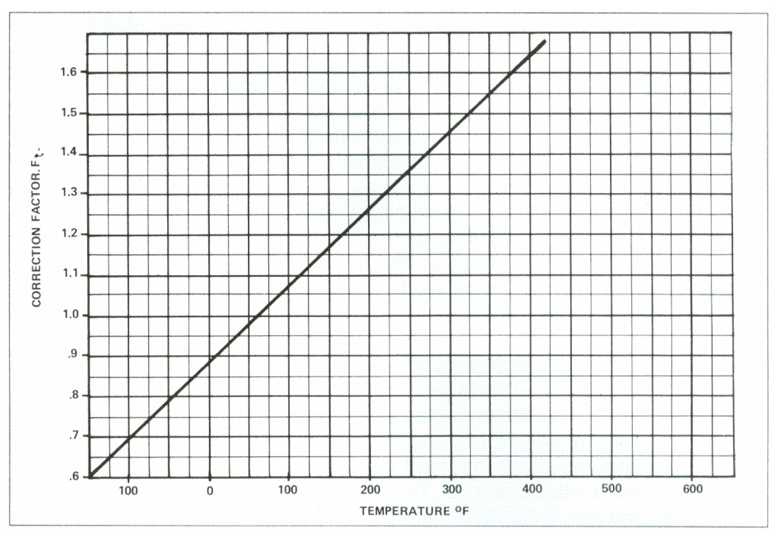
TEMPERATURE CORRECTION FACTOR CHART Fig. 5-FT Since the selector chart for gases (Chart A) is based on the air flow at 60°F, a correction factor is necessary when using other gases and
temperatures. Figures 5 and 6 determine these factors, corresponding to gas operating temperature and molecular weight. A table of molecular weights for common gases is found in Figure 7. When the known gas flow rate is multiplied by these correction factors, Ft and Fg, the equivalent air flow rate (EAFR=SCFM x Ft x Fg) is determined and the selector Chart A is ready for use.
|
|||||||||||||||||||||||||||||||||||||||||||||||||||||||||||||||||||||||||||||||||||||||||||||||||||||||||||||||||||||||
SOME USES OF INLINE SEPARATORS
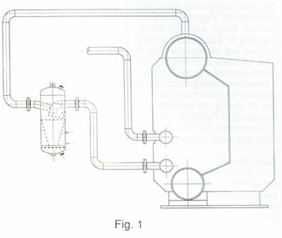
| INLINE SEPARATORS FOR PROTECTING BOILER SUPERHEATER FROM WET STEAM Often times the continual use of a boiler will cause the internals of the superheat section to foul and the boiler may become inefficient as far as the quality of steam leaving the boiler. Replacement of these internals in the boiler may become laborious and expensive. These internals are usually miniature centrifugal separators. As a suitable alternative to this, the use of an externally installed Penn Centrifugal Separator as shown in the drawing becomes an efficient means of producing very clean dry steam. The retrofit as shown in the drawing goes between the boiler steam Outlet and the Super-Heater Inlet. The effectiveness of this Steam Separator with the Penn Cone produces very high quality steam (less than 1 ppm total impurities) to protect the superheater section of a water tube boiler. This separator is designed and built to ASME Code, Sec. 1 (See Fig. 1) |
 |
|
BOILER STEAM HEADER WITH INLINE SEPARATOR INCREASES QUALITY OF STEAM |
||
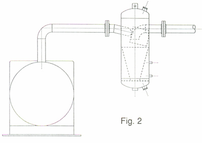 |
To provide clean dry steam from a low or high pressure boiler a Penn Centrifugal Steam Separator is installed on the steam header from the boiler. This Separator can provide steam of 99.8% quality. The drain of the separator can be piped back to the system or drain. (See Fig. 2) Other uses include cleaning steam prior to turbines, Autoclaves, and other steam powered equipment. |
|
AIR DRYER EFFECTIVENESS CAN BE IMPROVED WITH AN INLINE SEPARATOR |
||
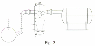
A Penn Inline Separator is often used between the compressor and the Air Dryer. The separator can clean moisture from the air before the air enters the dryer. The separator does not lower the dew point of the air, but can increase the efficiency or down time of the dryer. (See Fig. 3) Separators are also used prior to air operated equipment, on natural gas lines, or on other air or gas process. |
 |
|
P.O. BOX 340
Brookville, PA 15825
(814) 849-7328
Fax: (814) 849-4510
TOLL FREE: 1-888-PENN-SEP (7366-737)