|
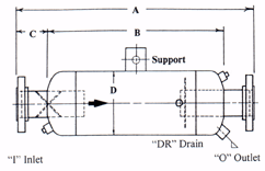
DIMENSIONS CHART "T" TYPE INLINES
|
| MODEL
NO. |
"A" |
"B" |
"C" |
"D" |
"I
& O" |
"DR"
|
| IS
3/4-3 |
11" |
7
1/2" |
12" |
3" |
3/4" |
3/4" |
| IS
1-4 |
15" |
10" |
14" |
4" |
1" |
3/4" |
| IS
1 1/4-5 |
17
1/2" |
12
1/2" |
15" |
5" |
1
1/4" |
3/4" |
| IS
1 1/2-6 |
21" |
15" |
15" |
6" |
1
1/2" |
3/4" |
| IS
2-6 |
21" |
15" |
18" |
6" |
2" |
1" |
| IS
2 1/2-8 |
28" |
20" |
20" |
8" |
2
1/2" |
1" |
| IS
3-10 |
31" |
23
1/2" |
21" |
10" |
3" |
2" |
| IS
4-12 |
38
1/2" |
28
1/2" |
25" |
12" |
4" |
2" |
| IS
5-16 |
45" |
34" |
32" |
16" |
5" |
2" |
| ISO
6-18 |
49" |
37
1/2" |
34" |
18" |
6" |
2" |
| ISO
8-24 |
65" |
51" |
46" |
24" |
8" |
2" |
| ISO
10-30 |
81
1/2" |
63
1/2" |
50" |
30" |
10" |
3" |
| ISO
12-36 |
97
1/2" |
76
1/2" |
66" |
36" |
12" |
3" |
| ISO
14-42 |
113" |
89" |
74" |
42" |
14" |
3" |
| ISO
16-48 |
128" |
102" |
78" |
48" |
16" |
3" |

| DIMENSIONS
"STRAIGHT THRU" INLINE SEPARATORS |
| MODEL
NO. |
"A" |
"B" |
"C" |
"D" |
"I
& O" |
"DR"
|
| ISH/D/U
2-6 |
32" |
24
1/2" |
3
3/4" |
6
5/8" |
2" |
3/4" |
| ISH/D/U 2 1/2-8
|
32" |
24
1/2" |
3
3/4" |
8
5/8" |
2
1/2" |
3/4" |
| ISH/D/U
3-8 |
32" |
24
1/2" |
3
3/4" |
8
5/8" |
3" |
1" |
| ISH/D/U
4-10 |
36" |
28" |
4" |
10
3/4" |
4" |
1
1/2" |
| ISH/D/U
5-12 |
38" |
30" |
4" |
12
3/4" |
5" |
2" |
| ISH/D/U
6-12 |
40" |
32" |
4" |
12
3/4" |
6" |
2" |
| ISH/D/U
8-16 |
48" |
40" |
4" |
16" |
8" |
2" |
| ISH/D/U10-20 |
60" |
48" |
6" |
20" |
10" |
2" |
| ISH/D/U
12-24 |
74" |
60" |
6" |
24" |
12" |
3" |
| ISH/D/U
14-30 |
90" |
78" |
6" |
30" |
14" |
3" |
| ISH/D/U
16-30 |
100" |
88" |
6" |
30" |
16" |
3" |
| ISH/D/U
18-36 |
108" |
92" |
8" |
36" |
18" |
3" |
| ISH/D/U
20-36 |
120" |
104" |
8" |
20" |
20" |
3" |
Suggested
Specifications
Furnish
and install as shown on plans a Centrifugal Entrainment Separator
either a (Model IS _____-_____ "T" Type Separator
for a horizontal line with a Penn Cone for Maximum Efficiency)
or (a "Straight Thru" Separator Model No. _____-_____
with PHB helical baffles Model ISH for Horizontal, ISU Up-flow,
or ISD Down-flow). Either should be properly sized for a (steam
flow rate _____#/hr.) Or (Air or other gas _____ SCFM at an
operating pressure of _____psig.
Separators
are to be constructed to ASME Code Sec. VIII Div. 1 for a
maximum operating pressure of (150) psig at 450 deg. F using
150# Flanged inlet & outlet connections), (250 psig at
450 deg. F with 300# flanged inlet and outlet connections),
or (600 psig at 500 deg F. on 2" and smaller threaded
inlet and outlet). Other pressure and temperature ratings
can be specially provided. Coupling Connections NPT threaded
would be supplied for the entrainment drain and inspection
ports. The exterior would include a shop primer finish. Central
hanger supports are provided on larger units.
Optional
accessories could include a (trap) suitably sized to allow
constant drainage of the separated liquid entrainment and
or a (level gauge) to show a liquid build up. |


